Short Work in Short Time

19 January, 21:51, by EvaB

Shawn signed up on Monday night of last week, and has already done a bunch of awesome projects.
This was an “up cycle” from old Ikea futon frames and a change table.

Shawn said “The project was made using wood collected from my children’s change table and two futon frames.

IMG_1558


The frame is already on the bottom and all that’s left to do is a vinegar and steel wool stain and then maybe a sealer. “

IMG_1560IMG_1561


The final table is 40″x 40″.

Wow!

Last night, Shawn was shaping a multi layered sheet of wood made from maple, cherry and walnut.

We would love to see what that turns out to be, too!

Thanks, Shawn!

Live Edge White Ash Tables

05 December, 14:47, by EvaB

Recently, Brett made some beautiful live edge furniture out of local white ash.  Live edges have minimal finishing to leave some of their natural contour, colour, and remnants of bark leaving a beautiful edge trim.

Congratulations, Brett!!

DSC01757DSC01754

DSC01751smaller table

DSC01753


Games in the Park – Wooden Block Stacking Game

11 May, 17:00, by Mark Zander

As a first in what is hopefully a series of “Giant Board Games to Play in the Park”, here is my take on that well known wooden-block-stacking-game.

I got all my inspiration from this Instructables Post.GiantJengawithDarwinandLiam

Materials Used :

6 – 8′ x 2″ x 4″ SPF (your standard 2×4)

1 can of MinWax Paste wax.

Shop Tools Used :

Chop saw

15″ Thickness Planer

BenchTop Belt Sander


First I set the right end stop of the Chop saw so that it was 10 1/2″ from the blade. This will allow me to make repeated cuts that are all the same length. I then positioned a roller stand to the left of the Chop saw and adjusted the height so it can support the weight of the 2×4 on the left in-feed side. This is needed as the 8 foot  2×4 is much too long to hold by hand safely on the Chop Saw.

Now it is just a matter of aligning the 2×4 on the stand and Chop Saw and pushing it up against the stop; make your cut; wait for the blade to stop and then clear the cut piece. You will be able to cut 9 ‘blocks’ out of one 2×4 (with a tiny bit left over.)

When you are finished cutting all 6 of the 2×4’s in to 10 1/2″ blocks you will need to smooth the top and bottom. A smooth top and bottom will make the game much easier as the blocks won’t catch on each other as then are removed from the stack.

You can smooth it with a sander. But I opted for using the Thickness Planer which will give you a very smooth surface very quickly.

I set the Thickness Planer to take off about 1/8″ off the top of the block and then ran all the blocks through once. I then set the Planer to take off 1/8″ the bottom and ran all the blocks through a second time. This left a mirror like finish on the blocks, as I had just replaced the blades the day before.

You will notice that the Thickness Planer has ‘sharpened’ the four edges and corners on both ends of the block. For safety I used the BenchTop Belt Sander to round over the edges and corners.

After sanding the edges the final step is to seal the wood. I chose to use a Paste Wax. It not only penetrates the wood but also creates a slippery surface which gives you just the right slip when trying to remove the blocks from a stack. I have not tried but I would think that varnish or shellac would be too “grippy” as surface and make removing the blocks much more difficult.

The only thing you need now is a bag or box to carry the blocks to the park and a level surface to play on. Oh, and a bunch of friends to play with!


-zander.

End Grain Cutting Board

13 October, 23:04, by Galen Fick

The first project I started when I joined Diyode was to make a few cutting boards for weddings. After a trial one to figure out the process, I set about making two identical boards.

First thing was to head down to A & M Wood Specialty in Cambridge to pick up some Rock Maple, Cherry and Walnut for the project.

IMG_0908

Milling the rough lumber is so satisfying. A few passes on the planer to bring the boards down to 1 3/4″ in thickness and a few passes over the jointer to get the sides clean and squared up.

IMG_0909

Next was to cut out the pieces for the glue ups. I had made a pattern that required two planks – one 3/4″ thick by 19 3/4″ and one 1 3/4″ by 10″.

IMG_0978

You I have them laid out here. Making two boards meant two of the 3/4″ panels and one 1 3/4″ panel (it was over 20″ so I could get enough for both boards out of it).

IMG_0979

I marked each piece with its order and orientation. I didn’t want to get mixed up over the multiple times I came into Diyode to do my glue ups.

IMG_0980

Here is the glue up for the panels. Hardwood cauls to keep it even while the 4 bar clamps did the bulk of the clamping work here. As this was going to be a cutting board it is important to use glue that is good indirect food contact. I used Titebond III.

IMG_0981IMG_0985

Next, I took all three panels back through the planer to clean up the top and bottom so they would be ready for the next glue ups.

IMG_0988

The final board will be 2″ thick so I needed to crosscut all the panels down to 2″ strips to get ready for the second glue up. The thicker panel all sliced up and divided to make the two boards. I wanted to keep the grain pattern consistent through the final board, so I marked the slices again so I could keep them in order and orientation.

IMG_0992IMG_0991

Here is the first look at the pattern of the final board laid out ready for glue. All the 2″ slices I made in the last round of cuts are turned on end to expose the end grain and give a consistent thickness. The pattern is made by alternating and flipping between one 1 3/4 slice and two 3/4 slices. (The burnout from the table saw is somewhat unavoidable, but with skill and experience it can certainly be improved)

IMG_0995IMG_0997

Coming out of the clamps. Now it is time for the most time consuming step: sanding. So very much sanding.

IMG_1012IMG_1013IMG_1014IMG_1015

So very much sanding. Here is a comparison between a completed side and one that hasn’t been started.

IMG_1006

The natural colours start to come out more once the sanding got up to 220 grit. You don’t really want to go more than that because the board is going to be used actively with knives, so it isn’t really worth the effort.

IMG_1030

After I was satisfied with the sanding job, I took it to the router table. I did a 1/4″ round over on the top edge, an 1/8″ round over on the bottom as well as routed out finger holds on the short edges that were about 1″ tall, and 4″ long. I also made use of one the coolest tools at Diyode – the laser CNC – to engrave the names of the bride and groom into the side of the board.

IMG_1032IMG_1033

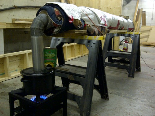
It was time to finish the board. With the end grain exposed, it will be a thirsty board, so I saturated it in 4 coats of mineral oil (food safe). For the final finish, I made some ‘bee butter’ by heating mineral oil in a double boiler and melted about a 1:6 ratio of beeswax into it. I made enough to give some to the couple for whenever the board needs a bit of moisture.

IMG_1034


Yurt Update

04 March, 20:34, by Andrew Afelskie

In the first yurt blog post there were photos and video of some steam bending action. I am glad that attempt was captured on video as that was the only successful session, the previous four were quite disappointing. However we are now above-average skilled steam benders and the next time, if ever we get inspired again, will be quite amazing indeed.

The result is a four foot diameter circle called a crown or in Mongolian, a ‘tono’. Once the two semi-circle pieces set in place around the former, which took over a week, we glued and drilled holes for dowels to secure the joint.

IMGP0003

Since this will form the top of the yurt where all the roof poles connect into, I drilled and chiseled 46 mortises around the tono, using modest hand tools.

IMGP0001

Then we harvested some willow from a friend’s farm to weave a simple dome shape.

IMGP0005

Voila, a yurt tono.

Diodes DIYode

22 February, 21:40, by EvaB

A while ago,  Ken Brown and I worked on a portable sign to promote DIYode at two events in the same week.  It was made by etching our logo into an acrylic panel, and setting that panel onto a strip of LED tape in a wooden base.  The sign has gone on to several more events, where it has drawn eyes from far away.

image2993image3003

It adorns our window at night, where the reflections from the lights wash up the blinds.

Thank you Ken Brown!

Have Seat, Will Race!

07 February, 20:50, by Mark Zander Tags:

I’ve had a life long love of cars and racing them. I’ve often dreamt of owning a nice sports car just to bring to the track on the weekends.
I can stop dreaming now. Cause the computer based racing simulators today are just as good of an experience as any sports car I will ever afford.

Building my own racing seat to go with rFactor as a computer racing simulator has been on my mind for years. So long in fact that I’ve dragged the passenger seat of a 1993 Honda Civic around with me since I junked it in the early 2000’s.
I finally had the time to build up something that will fit the bill. Here’s what I came up with :

Racing Seat 4

Here are some more photo’s.

There are still a few things I need to do before it is finished. Find a large enough monitor, mount the PC and paint it.
But it works pretty well as is.

I did not have any formal drawings before I built it. But it is very much based on a few existing Racing seats out there. Here are some links that helped me and may help you out.

http://insidesimracing.tv/forums/topic/4661-isr-diy-rig-1-the-deathmobile-wood-rig/
http://www.ricmotech.com/store/diy_chassis_plans/rs1_diy_sim_racing_cockpit_plans
www.thewayiplay.com/mainforum/index.php?topic=443.5
http://www.gtplanet.net/forum/showthread.php?t=259376

Come by during the DIYode Monday night openhouse (8pm-whenever) and give the seat a try!
If anyone is interested in making one of these for themselves, leave me a comment.

Mobile Robot Platform

31 January, 11:58, by Mark Zander Tags:

Who doesn’t like to play around with robots? Make them do cool stuff.
So when I saw a six-legged remote control bug (called an N.S.E.C.T) at the thrift store I thought; that would make a cool base for a robot. The NSECT is supposed to be remote control but this one did not come with the controller. But otherwise was complete and worked. Along with walking on six legs it has a front pincher and a rear six shot gatling gun.

First thing I did was take the entire thing apart. Here is a good page with a description and pictures.
The legs are moved with a complicated set of gears and cams by 2 DC motors. One motor from the left, one for the right. Perfect for something like a motor driver chip to handle.
I already had a Arduino Motor shield from Adafruit. But after some investigation I realized I’ll need something else. The Adafruit motor shield max’s out at 600mA per motor. The NSECT’s motors took 800mA+. I toyed with the idea of making an H-bridge motor controller from scratch but then saw a 2A motor shield from RobotShop in Quebec.
I ripped most of the NSECT’s guts out and wired in the motor shield and Arduino.

DIYode now has a good Robot Platform we can use to experiment with robots!
I plan to add some IR sensors so the robot will be able to detect objects. Plus a biggie is to get the pincher working, and I won’t forget about getting that gatling gun working!

Robot 2

Wood Bending with Steam!

24 January, 09:00, by Mark Zander Tags:

Erin and Andrew needed to build a circular crown for their yurt. So they decided to steam bend it in a wood streamer they put together one day at DIYode.

Steam bending

After 3+ hours of steam the wood planks were bent around the form.
You need lots of muscle and quite a few clamps!

steam bending

More Steam Bending pictures and some video.

DIYode Glows in the Dark

23 January, 23:32, by EvaB

Last Wednesday, I was reading through the morning’s DIYode IRC chat when I ran across an article that Jamie had mentioned.  Someone had made a very attractive faceplate for LED light to shine through, similar to the control panel on some electronics. What had made it special was the high heat paint sprayed onto the acrylic beforehand, which produced a sharp, clean image. The site is here: http://hackaday.com/2013/01/16/one-method-of-fabricating-translucent-faceplates/.

I got thinking that it would be interesting to make it wearable, like a necklace that glows. I asked the body of IRC chat people in our room what logo to use, and an answer came through just as I thought of the same one:  OUR LOGO!

I assembled the pieces, sprayed the paint, and enlisted the help of Mark Zander to help laser our logo onto small ovals.  He also completely laser etched an oval to act as a diffuser.  Mark worked on getting an itty bitty LED and an itty bitty resistor into the side of the etched oval.  Something wasn’t quite right.  We worked on it (well, mostly Mark worked on it) until about 9 that evening.  The prototype was still not done.

I went looking for “edge lit LED signs” in Google and found another site that was doing more or less the same thing http://grathio.com/2010/06/how_to_edge_lighting_displays/ .

I had some LEDs at the house given to me by Dan O’Connell from Kwartzlab in Kitchener.  I went to an electronics store to get a 3 Volt button battery, and tested the LEDs right in the store.  Lo and behold, the green LED was just right, as our logo is green (sometimes).

My plan was to use an unpainted acrylic oval, sanded on both sides, between the logos to act as a light diffuser.  This was similar to the one Mark had been working on.  Based on the second website, I thought that sanding both sides would produce better diffusion than laser etching for the sandwich layer, and it did produce a cloudy, whiter surface.  I put it between the logos to test, and it seemed to work well.

The LED got sanded and flattened with a Dremel tool.  After cutting out a well in the top, I put the logos back to back with the cloudy layer between them to make it reversible.  Sticky copper tape went around the perimeter, the LED got glued in with hot glue, the wires got soldered on, electrical tape went between the soldered ends, and then I popped a glass pony bead onto the exposed legs to hide them.

And voila! LED DIY on mechanged

Danny Dobbs happened to be in, and I used him as a model for the up close version:LED Diyode logochanged

All in all, this was a fascinating project.  I’ll happily be wearing it to several events soon.

Here it is in the daylight:

LED pendant